Tensioning with Magnetic Particle Brakes & Clutches
How to build precise unwinding/rewinding systems using simple, easy to use technology.
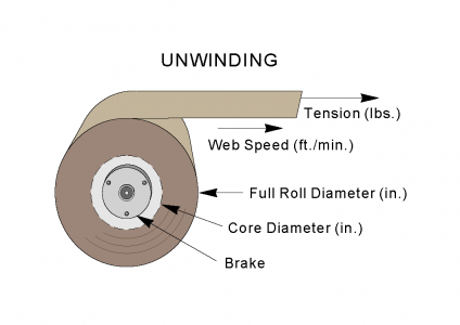
Magnetic particle brakes can provide an adjustable braking tension for unwinding film, wire or any web. Magnetic particle clutches can provide an adjustable tension for rewinding the same. Simple, effective tensioning systems can easily be built when each are teamed with a D.C. power supply and follower arm potentiometer or ultrasonic sensor for measuring the roll size.
Determine Tension
Determine the proper tension (in pounds, ounces, or grams) needed. The material manufacturer probably can recommend min./max. tensions. Tension can be experimentally measured with a force gage or simple fish scale.
Choose Roll Diameter
Decide on full roll diameter, and core (empty) diameters. Larger rolls require higher torque but rotate slower. Small cores require high RPM and lower torque. Avoid combining a very large full roll diameter and very small core, because a large range of torque and speed (RPM) is required.
Maximum Torque Required – Multiply the maximum web tension and maximum roll radius (diameter divided by 2).
For example, an 18″ roll diameter and 5 lbs. tension calculates to 18/2 x 5 = 45 lb.-inches torque.
Minimum Torque Required – Multiply the minimum web tension and minimum (core) radius.
For example, a 3″ core diameter and 2.5 lbs. tension calculates to 3/2 x 2.5 = 3.75 lb.-inches torque.
If a different diameter for the rewind roll is required (when an interleaf film is separated from the supply web), repeat the calculations for the new smaller rewind roll.
Determine RPM
Determine the web’s linear speed (feet/minute). Higher speed increases production, but puts higher thermal loads on the brake and clutch.
Maximum Roll RPM – occurs at the smallest roll diameter and the web’s highest linear speed. Calculate max. RPM by:
Max. RPM = 3.82 * (linear speed) / (core diameter)
For example, at a web speed of 200 feet per minute:
Max. RPM = 3.82 * 200 / 3” = 255
Minimum web speed occurs at full roll condition and slowest linear web speed. Magnetic particle brakes and clutches are smooth, but not perfectly smooth at very low slip RPM. Avoid applications with RPM below 25 RPM with elastic webs, as this can accentuate slip/stick characteristics.
Calculate Thermal Heat Dissipation
Slip torque and slip RPM produce heat. A clutch or brake must be large enough to dissipate the mechanical (thermal slip) input heat.
For brakes:
Slip heat (watts) = Tension (lbs.) x Web Speed (feet/minute) / 44.2
For brakes & clutches:
Slip heat (watts) = Torque (lb.-in.) x Slip RPM x 0.0118
For brakes slip RPM is simply the shaft RPM.
For clutches:
Slip RPM = (Input shaft RPM) – (Output shaft RPM)
Gearing affects RPM, but won’t affect heat dissipation requirements.
Often, a larger brake or clutch is needed so it’ won’t overheat. But the larger unit would have too much torque. Use a gearbox to multiply torque and decrease speed to the brake or clutch.
Power Supplies – Constant Tension Control
For constant tension winding, applied torque to the roll needs to vary in proportion to the roll diameter. Use either an ultrasonic sensor or follower arm potentiometer to measure the diameter of the roll.
Typically, the ultrasonic sensor will output a 0-10 volt control signal in proportion to the roll diameter. This signal then can be sent to some power supplies that have a scaling adjustment for varying desired tension or the ultrasonic sensor’s 0-10 volt control signal can also be fed into a universal signal conditioning board for scaling. The board’s 0-10 volt output can than control most constant current D.C. power supplies.